- 您现在的位置:买卖IC网 > Sheet目录109 > SBLB1640CTHE3/81 (Vishay General Semiconductor)DIODE SCHOTTKY 40V 16A TO-263AB
SBL(F,B)1630CT & SBL(F,B)1640CT
Vishay General Semiconductor
www.vishay.com For technical questions within your
region, please contact one of the following:
PDD-Americas@vishay.com, PDD-Asia@vishay.com, PDD-Europe@vishay.com
Document Number: 88727
Revision: 07-May-08
2
Note:
(1) Pulse test: 300
μs pulse width, 1 % duty cycle
Note:
(1) Automotive grade AEC Q101 qualified
RATINGS AND CHARACTERISTICS CURVES
(TA
= 25 °C unless otherwise noted)
ELECTRICAL CHARACTERISTICS (TC
= 25 °C unless otherwise noted)
PARAMETER TEST CONDITIONS SYMBOL VALUE UNIT
Maximum instantaneous forward voltage per diode (1)
8.0 A V
F
0.55 V
Maximum instantaneous reverse current at rated DC
blocking voltage per diode (1)
TC
= 25 °C
TC
= 100 °C
IR
0.5
50
mA
THERMAL CHARACTERISTICS (TC
= 25 °C unless otherwise noted)
PARAMETER SYMBOL SBL SBLF SBLB UNIT
Typical thermal resistance from
junction to case per diode R
θJC
2.0 4.0 2.0 °C/W
ORDERING INFORMATION
(Example)
PACKAGE PREFERRED P/N UNIT WEIGHT (g) PACKAGE CODE BASE QUANTITY DELIVERY MODE
TO-220AB SBL1630CT-E3/45 1.85 45 50/tube Tube
ITO-220AB SBLF1630CT-E3/45 1.99 45 50/tube Tube
TO-263AB SBLB1630CT-E3/45 1.35 45 50/tube Tube
TO-263AB SBLB1630CT-E3/81 1.35 81 800/reel Tape and reel
TO-220AB SBL1630CTHE3/45
(1)
1.85 45 50/tube Tube
ITO-220AB SBLF1630CTHE3/45
(1)
1.99 45 50/tube Tube
TO-263AB SBLB1630CTHE3/45
(1)
1.35 45 50/tube Tube
TO-263AB SBLB1630CTHE3/81
(1)
1.35 81 800/reel Tape and reel
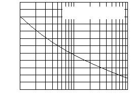
Figure 1. Forward Current Derating Curve
0
4
8
12
20
0
50
100
150
16
Resistive or Inductive Load
A
v
erage For
w
ard C
u
rrent (A)
Case Temperature (°C)
Figure 2. Maximum Non-Repetitive Peak Forward Surge
Current Per Diode
0
50
150
100
250
200
300
1
100
10
TJ
= T
J
Max.
8.3 ms Single Half Sine-Wave
Number of Cycles at 60 Hz
Peak For
w
ard S
u
rge C
u
rrent (A)


发布紧急采购,3分钟左右您将得到回复。
相关PDF资料
SBLB2040CTHE3/81
DIODE SCHOTTKY 40V 20A TO-263AB
SBR0330CW-7
DISCRETE DIODE ARRAY
SBR05U20SN-7
DIODE SBR 0.5A 20V SC59
SBR10100CTFP
DIODE SBR 10A 100V TO220-3
SBR10100CTL-13
DISCRETE DIODE ARRAY
SBR10120CTL-13
DISCRETE DIODE ARRAY
SBR10150CTL-13
DISCRETE DIODE ARRAY
SBR10200CTB-13-G
DIODE SBR 10A 200V D2PAK
相关代理商/技术参数
SBLB2030CT
制造商:GOOD-ARK 制造商全称:GOOD-ARK Electronics 功能描述:Dual Low VF Schottky Barrier Rectifiers
SBLB2030CT/45
功能描述:肖特基二极管与整流器 20 Amp 30 Volt Dual RoHS:否 制造商:Skyworks Solutions, Inc. 产品:Schottky Diodes 峰值反向电压:2 V 正向连续电流:50 mA 最大浪涌电流: 配置:Crossover Quad 恢复时间: 正向电压下降:370 mV 最大反向漏泄电流: 最大功率耗散:75 mW 工作温度范围:- 65 C to + 150 C 安装风格:SMD/SMT 封装 / 箱体:SOT-143 封装:Reel
SBLB2030CT/81
功能描述:肖特基二极管与整流器 30 Volt 20 Amp Dual Common-Cathode RoHS:否 制造商:Skyworks Solutions, Inc. 产品:Schottky Diodes 峰值反向电压:2 V 正向连续电流:50 mA 最大浪涌电流: 配置:Crossover Quad 恢复时间: 正向电压下降:370 mV 最大反向漏泄电流: 最大功率耗散:75 mW 工作温度范围:- 65 C to + 150 C 安装风格:SMD/SMT 封装 / 箱体:SOT-143 封装:Reel
SBLB2030CT-E3/45
功能描述:肖特基二极管与整流器 20 Amp 30 Volt Dual RoHS:否 制造商:Skyworks Solutions, Inc. 产品:Schottky Diodes 峰值反向电压:2 V 正向连续电流:50 mA 最大浪涌电流: 配置:Crossover Quad 恢复时间: 正向电压下降:370 mV 最大反向漏泄电流: 最大功率耗散:75 mW 工作温度范围:- 65 C to + 150 C 安装风格:SMD/SMT 封装 / 箱体:SOT-143 封装:Reel
SBLB2030CT-E3/81
功能描述:肖特基二极管与整流器 30 Volt 20 Amp Dual Common-Cathode RoHS:否 制造商:Skyworks Solutions, Inc. 产品:Schottky Diodes 峰值反向电压:2 V 正向连续电流:50 mA 最大浪涌电流: 配置:Crossover Quad 恢复时间: 正向电压下降:370 mV 最大反向漏泄电流: 最大功率耗散:75 mW 工作温度范围:- 65 C to + 150 C 安装风格:SMD/SMT 封装 / 箱体:SOT-143 封装:Reel
SBLB2030CTHE3/45
功能描述:肖特基二极管与整流器 30 Volt 20 Amp Dual Common-Cathode RoHS:否 制造商:Skyworks Solutions, Inc. 产品:Schottky Diodes 峰值反向电压:2 V 正向连续电流:50 mA 最大浪涌电流: 配置:Crossover Quad 恢复时间: 正向电压下降:370 mV 最大反向漏泄电流: 最大功率耗散:75 mW 工作温度范围:- 65 C to + 150 C 安装风格:SMD/SMT 封装 / 箱体:SOT-143 封装:Reel
SBLB2030CTHE3/81
功能描述:肖特基二极管与整流器 30 Volt 20 Amp Dual Common-Cathode RoHS:否 制造商:Skyworks Solutions, Inc. 产品:Schottky Diodes 峰值反向电压:2 V 正向连续电流:50 mA 最大浪涌电流: 配置:Crossover Quad 恢复时间: 正向电压下降:370 mV 最大反向漏泄电流: 最大功率耗散:75 mW 工作温度范围:- 65 C to + 150 C 安装风格:SMD/SMT 封装 / 箱体:SOT-143 封装:Reel
SBLB2040CT
制造商:VISHAY 制造商全称:Vishay Siliconix 功能描述:SCHOTTKY RECTIFIER
